Membrane System Design: Reverse Osmosis
Reverse osmosis (RO) systems can seem intimidating. However, this technology has been around for decades and is used globally in all types of industries. Understanding the basics of how RO membranes work, and the mechanisms of the RO process are the first steps to system optimization.
Types of RO Membranes and Terminology
First, let’s describe common terminology used in the RO industry:
- Recovery is the percentage of clean water (permeate) a system produces from the feed water. It depends on several factors including salt content of the water, system design and amount of permeate water a membrane can produce.
- Rejection is the percentage of salt removed by a membrane from the permeate stream. So, if a membrane has 99% rejection, that means 99% of the salts are removed from the permeate water.
- Salt Passage is the opposite of rejection and is a percentage of dissolved solids in the feedwater allowed to pass through a membrane into the permeate. If a membrane has 99% rejection, that means the salt passage to the permeate would be 1%.
- Applied Pressure is the amount of pressure applied to the system using a high-pressure pump to overcome the membrane’s osmotic pressure.
- Osmotic Pressure is the pressure that must be applied to prevent pure water from backflowing across a membrane. Osmotic pressure increases as the amount of total dissolved solids (TDS) in the feedwater increases. Typically, you need 11 psi (0.76 bar) for every 1,000 mg/L of TDS.
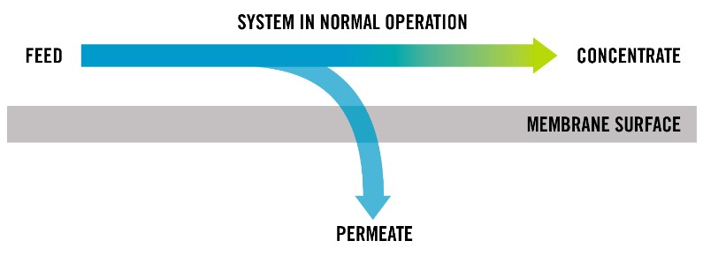
- Flows/Streams – RO systems are typically operated in a cross-flow configuration where three water streams exist. The first is the feed stream which splits into two other streams: clean water known as permeate and the rejected water known as concentrate. Flow is typically measured in gallons per minute (gpm).
The most common type of RO membranes are brackish, seawater and nanofiltration (NF). To determine the best membrane for your system, consider your feedwater source, desired recovery, water quality, and energy requirements.
- RO brackish membranes are typically used with brackish feedwaters containing a relatively low (TDS) compared to seawater. They require a low amount of pressure (125 – 250 psi) while maintaining a high salt rejection (>95 – 99% depending on certain conditions) and high system recoveries, ≥75%.
- Seawater membranes are used with seawater or feedwaters with a high TDS. Since those feedwaters have a TDS of 35,000 mg/l or greater, seawater membranes require a much higher pressure to operate (800 – 1200 psi) and can maintain a high rejection (>99.5%); however, their recoveries are lower than that of brackish membranes, between 50 – 70%.
- NF is a similar technology to RO but it has a lower rejection of monovalent ions such as sodium chloride. It rejects divalent ions such as CaSO4 very effectively and organic macromolecules to varying extents depending on the model. For example, some NF membranes can reject >97% of magnesium sulfate (MgSO4) but only 85% – 95% of sodium chloride (NaCl). This is because NaCl is smaller than MgSO4. However, there are some sulfate-rejecting membranes that only reject about 25% of sodium chloride, so the properties of NF are very varied. Required pressures to run NF membranes are lower than RO membranes on the same feedwater as the monovalent ions are not fully rejected.
Membrane Material
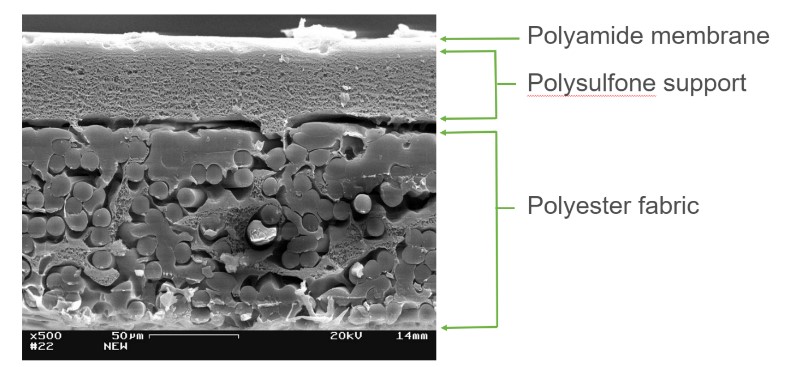
Membrane manufacturer’s today construct thin-film composite (TFC) RO membranes consisting of three layers: the extremely thin polyamide top barrier, the polysulfone support layer and polyester layer. The semi-permeable polyamide barrier prevents molecules with molecular weights greater than 100 from passing through. Water molecules easily diffuse through the polyamide layer, providing pure water on the opposite side.
Construction of Spiral-Wound RO Membranes
TFC membranes are packed into a spiral-wound configuration, allowing for several advantages compared to other configs: lower replacement costs, less space needed, simpler plumbing systems and more design freedom. Typical diameters of these spiral-wound elements for commercial use consist of 4-inch and 8-inch elements. These sizes were standardized early in the industry because of their efficient energy use, productive surface area, reliable performance, and existing infrastructure.
Elements are comprised of several components: outer wrap casing, anti-telescoping devices, brine seal, membrane leaves, feed spacers, glue seals, permeate carriers and the permeate water tube.
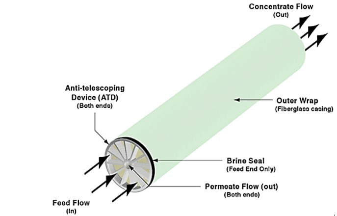
Figure 3 shows the external components of elements. The outer wrap may be tape, fiberglass, or a polypropylene mesh (also known as fullfit) and keeps the element together in the spiral-wound shape. The anti-telescoping devices (ATDs) stabilize the components of the element and prevent shifting of the internal mechanical components under pressure, also known as telescoping. The brine seal wraps around the feed side ATD and guarantees the feedwater flows into the element’s internal components.
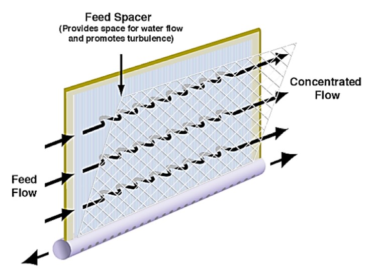
Figure 4 demonstrates the purpose of the element’s feed spacers which provide a space for water to flow as well as promote turbulence, helping the water flow much faster. Since RO membrane elements utilize crossflow filtration, the fast-moving water pushes off foulant and salts forming on the membrane surfaces.
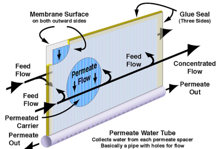
Figure 5 shows one membrane leaf and water flow interactions within and around that leaf. There may be up to 30 leaves in a single element (depending on the manufacturer). Each membrane leaf consists of a permeate carrier in between two active membrane surfaces. Once the water permeates through the membrane surface, the permeate carrier collects the clean water and directs it toward the permeate water tube. The leaves are glued together on the feed and concentrate side as well as the outer edge but are not glued where the permeate carrier attaches to the permeate water tube.
RO Pressure Vessels and System Design
Cylindrical RO pressure vessels house the elements, and their construction material relies on the operating pressure, vibrations, temperatures, feedwater and chemicals entering the system. They also require some sort of corrosion resistance due to the high salt content of water streams and chemical cleaning. Vessels fabricated from filament-wound glass reinforced plastic (FRP) have been used for systems from 100 psi up to 1200 psi operation. These FRP vessels are inherently non-corrosive and have a smooth and precise inside surface for optimum membrane loading and sealing. Stainless steel vessels are typically only used these days for steam sterilized systems like found in dairy applications.
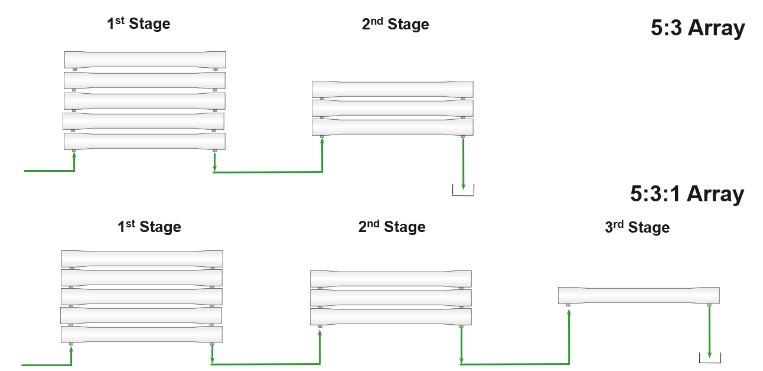
The number of elements that go into a vessel depends on how much water is needed in the permeate stream, the average membrane flux of the system, required active membrane surface and the type of elements. You can use multiple hydraulic programs that run calculations for the number of elements per vessel, number of vessels for stages, and number of stages needed for the whole system. Single stage systems are typically used with low recovery systems (e.g., seawater desalination) while multi-stage systems are used to acquire a higher recovery. Two examples of system arrays are shown in the figure below. Each vessel in one stage is set up in parallel while the separate stages are set up in series. The latter stages require fewer vessels as the volume remaining on the feed/brine side reduces as permeate is produced. In the example below, since the 1st stage has five vessels and the 2nd stage has 3 vessels, the system is a 5:3 array.
Balancing the permeate flow rate between stages is important for a system to have a good average flux. Typically, the permeate flow rate will be lower toward the tail elements (elements located toward the end of each vessel) compared to the lead elements. This is due to the concentration of salts being higher toward the tail elements, which increases the osmotic pressure and makes it harder for those elements to produce permeate water. It may be necessary to boost the feed pressure between stages to ensure a balance flux across all membranes.
The 5:3 array system above should not be confused with a two-pass system, which is the combination of two RO systems where the permeate water from the first system becomes the feed for the second system. In this case, the water is “passing” through two RO systems. Two-pass systems are used in applications that need extremely high quality permeate water.
Post Treating Permeate Water
After the clean water is collected, it is suitable for various applications such as: drinking water, production of food and beverages, pharmaceutical development and experiments, semiconductor manufacturing and many more. However, most of these applications require further treatment before the water is ready for use.
Ultraviolet (UV) disinfection kills or deactivates any remaining bacteria, viruses, or other microorganisms, providing an extra layer of protection for industries that require high microbiological purity.
Ion exchange (IX) resins remove trace amounts of unwanted dissolved minerals, like silica from water used in boiler loops.
Electrodeionization (DI) uses electricity, ion exchange membranes and resin that removes ionized molecules from water, resulting in extremely pure water used in laboratory and scientific applications.
Remineralization involves the addition of certain minerals for taste and health reasons, like in drinking water.
Concentrate Water Disposal
The concentrated wastewater stream must be taken into consideration since it contains the salts from the feed that have been retained by the membranes at much higher concentrations than the feed water. For some RO systems that are small-scale or residential, the concentrate can be discharged straight to the local drain or sewage. Depending on the environmental regulations and quality of the concentrate water, it can be discharged to surface waters. Zero liquid discharge (ZLD) systems minimize the amount of liquid waste by evaporating the concentrate and recovering the leftover salts as waste. However, some concentrates have dried salts that are a valuable resource and will be useful in some applications. It is also important to consider the length of the concentrate waste line because the salts may precipitate from the water and form deposits, or scale, on the piping, effectively blocking the exit flow of the system. It is always important to follow local regulations and environmental guidelines when disposing of waste streams.
For maintenance and cleaning, treatment solutions such as antiscalant and clean-in-place (CIP) chemicals are used. If a CIP cannot be run on the RO system, Avista offers an off-site cleaning and restoration service (OSCAR) to clean the membranes in your system.
Designing an RO system requires much customization and should not be built the same exact way every time. These processes require different pre-treatment, construction materials, membranes, chemicals and more.